Better, faster, and more versatile: Semi-automatic phased array testing on wheelset components
Service, repair, and continuous improvement are essential tools in the routine maintenance of wheelset components. So too is non-destructive material testing! The use of phased array technology, recognised in the medical field, offers significant advantages.
Dr. Ingo Poschmann, Managing Director, W.S. Werkstoff Service GmbH
Wheels and shafts are critical safety components. Their high level of safety is achieved through high-performance materials, advanced manufacturing processes, durable design and modern routine maintenance methods. This is complemented by regular non-destructive material testing (NDT), which is used to detect damage that could arise from unexpected operating conditions.
Further development of previous ultrasonic testing
Ultrasonic testing has been an established test method for wheelset components for decades. As part of the inspection method, Phased Array Ultrasonic Testing (PAUT) technology, recognised in the medical field, has been further developed in recent years. This technique combines high reliability with short inspection times.
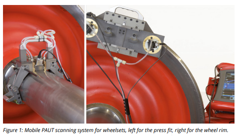
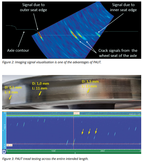
Figure 1 depicts a mobile, PAUT-based scanning system for wheelsets. PAUT technology is an imaging technique: Signals generated by a defect or by the geometry are depicted as coloured displays with direct reference to the component geometry. This is particularly useful if drawings are imported into the test device and the contours of the component compared with the PAUT signals during the test. This is clearly shown in Figure 2. Comparing the displays of the inner and outer wheel seat edge with the shaft contour allows for quick orientation for testing staff and an immediate check of the test results.
In this example, the test area is a wheel-shaft interface fit, i.e. the connecting line between the two wheel seat edges. All PAUT signals that have become visible on this line indicate cracks. This imaging signal visualisation greatly assists the inspector
and facilitates the detection of defects.
Other advantages of such a test system include:
- Modular design: Various inspection concepts can be implemented with a single hardware and software base, including mobile manual inspections and test benches with several simultaneously operating probes.
- Shorter inspection times: Excellent defect detection goes hand in hand with a significant reduction in inspection times compared to conventional manual inspection. A single scan with PAUT can replace many conventional inspection processes
- Automated report generation: The software of modern PAUT systems allows customizable and paperless inspection reports to be generated automatically.
- Raw data acquisition and storage: As PAUT probes are operated in conjunction with displacement transducers, all test data can be recorded and stored with pinpoint accuracy.
- Separation of testing and evaluation: If raw data is recorded and the correct coupling of probes is verified, then testing and evaluation can be separated in terms of time. This makes it possible to increase the effectiveness and flexibility of the testing process.
- Increased POD: The hardware and software of the PAUT systems make it possible to significantly increase the probability of detection of defects (POD) compared to conventional UT systems.


Full strength when coupled with web transducers
PAUT systems demonstrate their strengths in particular when they are coupled with position encoders. Figure 3 depicts a reference wheel with artificial defects of varying depth D and length L. These defects are distributed in groups over the running surface and intended length of the wheel. The PAUT probe (not shown) is located on the inner face of the wheel.
Figure 3 shows the recorded scan, which covers the whole tread over the entire intended length. All artificial defects are detected in a single scan lasting around one minute, even though some of them are very small. In addition, this scan allows the length and depth of the artificial defects to be estimated on the basis of the display length and the color-coded signal height.
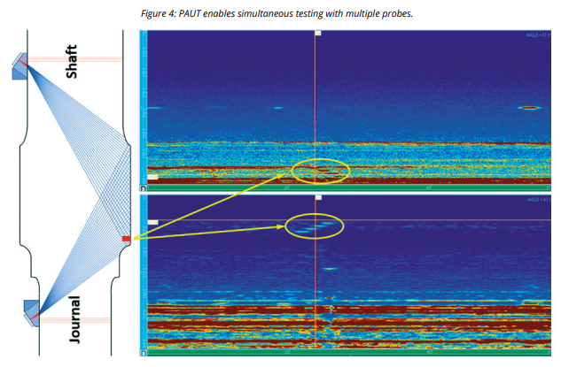
Figure 4 shows a setup for testing the interference fit with the two probes working simultaneously. A phalanx of several reflectors is located very close to the outer edge of the wheel seat.
The test head positioned on the shaft only faintly recognizes these reflectors. The reason: The reflectors are virtually “outshone” by the echo from the outer edge of the wheel seat. In contrast, the outer wheel seat corner is practically not a reflector for the probe on the leg. The phalanx can therefore be recognized clearly.
Multiple probes maximize information gain
The advantage of testing with two probes working simultaneously is obvious: Both probes constantly support and corroborate each other. In this way, you get maximum information and significantly improve the POD.
Our conclusion: Testing with phased array ultrasonic offers maximum safety. This includes high testing speed, full access to reliable test data, and flexible use of the testing systems.

